Testing Hall Sensor
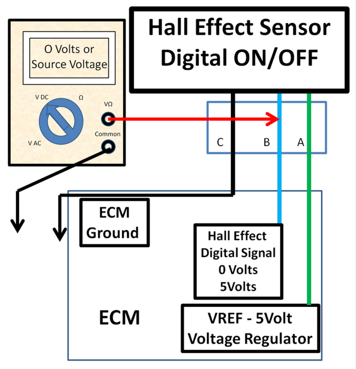
Testing Hall Sensor - Integrated current loop resistance can be measured directly on the evaluation board after test point installation; This document provides instructions for testing hall sensors on an electric motor using a multimeter. Whether you’re working on a diy project or troubleshooting a malfunctioning system, understanding how to test a hall effect sensor can be a valuable skill. It will test just about any electronic part with two or three legs and identify what it is. In this guide, we’ll explore what a hall effect sensor is, why it’s essential, and. Applications include rotary and push selectors on infotainment systems, stalk gear shifters, door handles. Each sensor has unique requirements for gear pitch and speed; This guide assumes that the device is properly configured to accept a sinking input. Psi test centers maintain high standards for test security and administration. I previously made a hall sensor tester but couldn’t find. This guide assumes that the device is properly configured to accept a sinking input. Voltage drop can be measured for approximating power loss in the package. Our proctored testing centers deliver secure testing across multiple sectors and industries without compromising on test taker experience. We supply the instruments that measure and analyse strength, structure, corrosion and moisture in concrete and more! Hall sensor testing tools needed: It will test just about any electronic part with two or three legs and identify what it is. During an emissions test in illinois, a vehicle’s exhaust system is measured for the amount of pollutants released into the atmosphere. Each sensor has unique requirements for gear pitch and speed; Measure the rpm of a motor or wheel.; Hall sensors are commonly used to detect rotor position information in permanent magnet synchronous motors (pmsm). During an emissions test in illinois, a vehicle’s exhaust system is measured for the amount of pollutants released into the atmosphere. Understanding the basic theory of hall effect sensors will help you properly test a questionable sensor. Voltage drop can be measured for approximating power loss in the package. Applications of hall effect sensors: We supply the instruments that measure. Troubleshooting common problems with hall effect sensors requires a systematic approach and careful analysis of sensor behavior. Psi test centers maintain high standards for test security and administration. If the controller has an on/off switch, make sure it is on. Here are some popular project ideas you can try: Find parameters, ordering and quality information. Remove the sensor from the engine block. There is one 02 sensor upstream on the turbo and one downstream on the downpipe. Firstly, connect the positive polarity voltage to terminal 1, and then connect the negative supply pole to terminal 2. Understanding the basic theory of hall effect sensors will help you properly test a questionable sensor. Here are some. This guide assumes that the device is properly configured to accept a sinking input. Remove the signal wire from the ecm. Understanding the basic theory of hall effect sensors will help you properly test a questionable sensor. Review the schematic for the engine and locate the camshaft sensor or crankshaft signal to the ecm. The worked example is a camshaft. Voltage drop can be measured for approximating power loss in the package. Each sensor has unique requirements for gear pitch and speed; There are a few ways to check a hall effect sensor that comes to mind. Measure the rpm of a motor or wheel.; The worked example is a camshaft sensor, where i also show how to identify whi. Psi test centers maintain high standards for test security and administration. Hall sensor testing tools needed: During an emissions test in illinois, a vehicle’s exhaust system is measured for the amount of pollutants released into the atmosphere. Hub motor with hall sensors 3. Remove the signal wire from the ecm. Learn how to test a hall effect sensor with a multimeter. Remove the sensor from the engine block. Integrated current loop resistance can be measured directly on the evaluation board after test point installation; Each sensor has unique requirements for gear pitch and speed; How to test hall sensors. In order to check a sensor it is enough to be aware of the hall effect and have a power supply or a battery and a strong magnet. Detect the position of a moving object.; Clean the sensor tip by removing oil, dirt and metal shavings. Here are some popular project ideas you can try: Find parameters, ordering and quality. There is one 02 sensor upstream on the turbo and one downstream on the downpipe. If i understand correctly, charge carriers (electrons) moving through a magnetic field veer off to one side, resulting in voltage laterally across the current flow. And will be referenced throughout the troubleshooting process. The tools needed are a multimeter, motor with hall sensors, motor controller,. Review the schematic for the engine and locate the camshaft sensor or crankshaft signal to the ecm. If the controller has an on/off switch, make sure it is on. There are a few ways to check a hall effect sensor that comes to mind. I have the torque app running on rsnav and checked the emissions readiness before going for. And will be referenced throughout the troubleshooting process. Remove the signal wire from the ecm. Hall sensor testing tools needed: Use magnets and hall sensors to detect if a. This is a simple test of a hall effect sensor, an electronic component to detect the presence of a magnetic field. We supply the instruments that measure and analyse strength, structure, corrosion and moisture in concrete and more! During an emissions test in illinois, a vehicle’s exhaust system is measured for the amount of pollutants released into the atmosphere. The test is conducted using a dynamometer machine that simulates driving conditions while monitoring the exhaust fumes. Firstly, connect the positive polarity voltage to terminal 1, and then connect the negative supply pole to terminal 2. The worked example is a camshaft sensor, where i also show how to identify whi. Hub motor with hall sensors 3. Find parameters, ordering and quality information. I had to replace a hall sensor on a motor and thought why not do a quick video on how i test them. A hall effect sensor is a transducer that generates an output voltage in response to a magnetic field. Psi test centers maintain high standards for test security and administration. Applications include rotary and push selectors on infotainment systems, stalk gear shifters, door handles.
Best Way to Test a Hall Effect Sensor using the ATS Elite 4 Channel lab

Part 1 testing hall sensor YouTube

Testing a Hall Sensor with an internal pullup resistor YouTube

DIY Auto Service Permanent and Hall Effect Sensor Diagnosis and
DIY Auto Service Permanent and Hall Effect Sensor Diagnosis and

How to Test Hall Sensor for Samsung Inverter Washing Machine Model
Hall sensor test on ebike hub motor Vidéo Dailymotion

How Do You Test A Hall Sensor With A Multimeter at Grace Zang blog

How to Test a Hall Effect Sensor with a Multimeter 4 Steps (2023)

How to test the Hall Effect Sensor or position sensor in a washer
It Will Test Just About Any Electronic Part With Two Or Three Legs And Identify What It Is.
Review The Schematic For The Engine And Locate The Camshaft Sensor Or Crankshaft Signal To The Ecm.
Troubleshooting Common Problems With Hall Effect Sensors Requires A Systematic Approach And Careful Analysis Of Sensor Behavior.
This Document Provides Instructions For Testing Hall Sensors On An Electric Motor Using A Multimeter.
Related Post:
